
Sponsored

Improved Racing CCS Catch Can

timestamped

Senior Member
Joined
Mar 19, 2024
Threads
2
Messages
139
Reaction score
161
Location
DC
Vehicle(s)
‘24 boost blue FL5, ‘15 tuxedo black FoST3
In the OEM configuration, it is simply a straight hose connection between two points (out from the head and directly into the intake manifold). Under boost conditions, it would make sense to add an inline check valve so pressure from the intake manifold does not pressurize the head at the same time.

Thoughts as to why Honda did not simply include a check valve between these two hose connection points to reduce/prevent pressurizing the head while under boost? Why not just close off the intake manifold connection entirely and simply add a breather filter on the head connection itself?

I really like the design/functionality of the Improved Racing CCS but don't understand why a check valve was not included for this particular installation location. On a related note, has anyone used this particular catch can on the other intake side to catch oil vapors that would otherwise be reintroduced into the intake track? I have not heard of anyone on this forum talking about that aspect where for example a drain cock or weeping hole would be needed on the lower section of the intercooler to drain.
There is a PCV valve in the valve cover, Part no. 17130-RPY-G01

Vacuum from the intake manifold draws flow from the valve cover, with the other side that connects between the intake and turbo inlet providing an input of metered air. In addition to relieving crankcase pressure, this actively pulls out water and fuel vapor that might otherwise condense and fall back into the oil pan.

When the PCV valve (or a check valve after the catch can) is closed, the flow doesn’t just completely reverse to go back into the turbo inlet, because it’s like having only one window open in the house. Air doesn’t circulate like if you have two open windows, hence why CCV cans don’t collect much.

I also think there is an issue with running too long of hoses to a can vs the short section normally between the valve cover and the intake, I think @PointByPatrol mentioned it.
Sponsored

 

blueroadster

Senior Member
Joined
Apr 19, 2024
Threads
29
Messages
659
Reaction score
941
Location
MD
Vehicle(s)
2024 Civic Type R, 2026 Passport TSE, 2026 Pilot BE, 1964 Impala SS
There is a PCV valve in the valve cover, Part no. 17130-RPY-G01

Vacuum from the intake manifold draws flow from the valve cover, with the other side that connects between the intake and turbo inlet providing an input of metered air. In addition to relieving crankcase pressure, this actively pulls out water and fuel vapor that might otherwise condense and fall back into the oil pan.

When the PCV valve (or a check valve after the catch can) is closed, the flow doesn’t just completely reverse to go back into the turbo inlet, because it’s like having only one window open in the house. Air doesn’t circulate like if you have two open windows, hence why CCV cans don’t collect much.

I also think there is an issue with running too long of hoses to a can vs the short section normally between the valve cover and the intake, I think @PointByPatrol mentioned it.
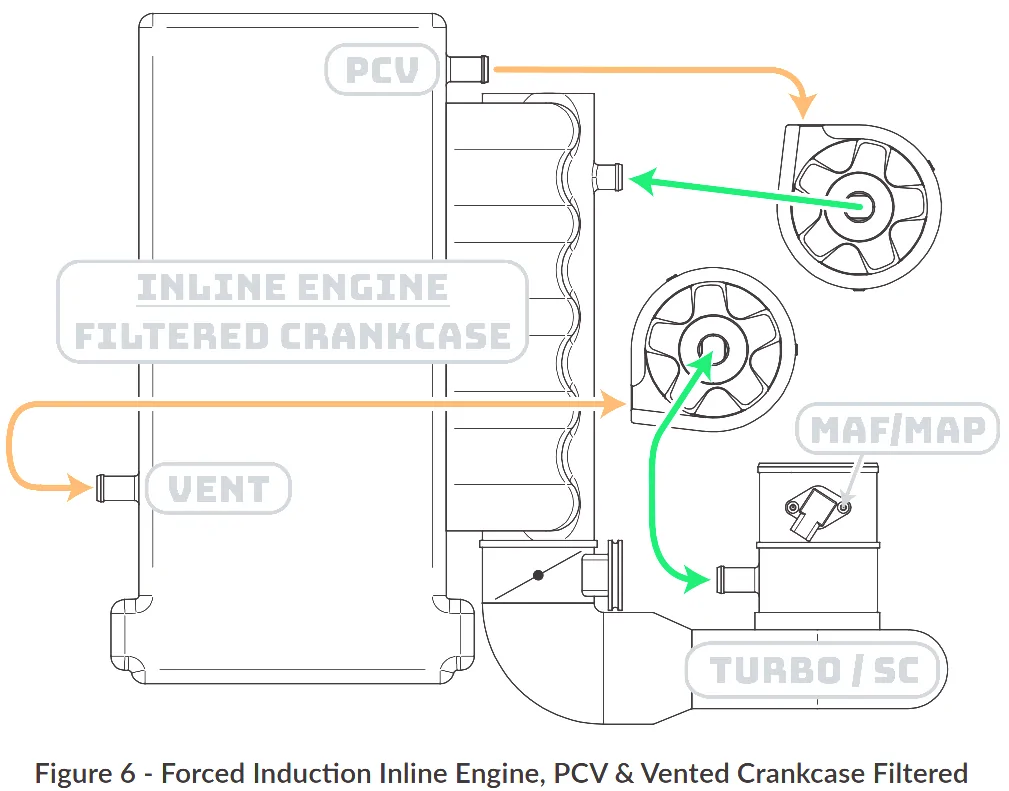
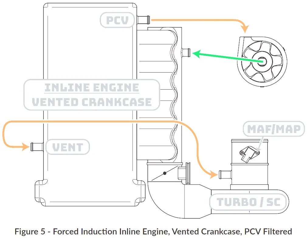
Thanks for the explanation...My last post was a confusing mess and I was not aware that the PCV valve was in the cylinder head cover itself. Here is take two. For the FL5, the Improved Racing CCS is installed inline on the PCV hose connection as depicted in this PIC (PCV Valve open when the intake manifold pulls a vacuum...PCV Valve closed when intake manifold pressure is greater than crankcase pressure from the other side):
11th Gen Honda Civic Improved Racing CCS Catch Can PCV_Filtered


That said, when under boost and the PCV Valve is closed, excess crankcase pressure is released from the CCV and reintroduced into the intake track after the MAF and before the turbo. The following PIC shows a dual catch can setup where one is installed inline on the PCV hose connection and the other on the CCV hose connection:
11th Gen Honda Civic Improved Racing CCS Catch Can PCV_and_CCV_Filtered

If only one Improved Racing CCS were used, why install it inline on the PCV hose connection instead of inline on the CCV hose connection? It would seem that installing on the CCV hose connection would be more effective at keeping the intake track leading all the way to the intake manifold clean. Said another way, catch can on the PCV side filters during idle/vacuum conditions feeding directly into the intake manifold whereas catch can on the CCV side filters during boost conditions feeding directly into the intake track after the MAF and before the turbo.
 

HondaHoon

Senior Member
Joined
Jul 18, 2025
Threads
15
Messages
443
Reaction score
364
Location
Western Maryland, USA
Vehicle(s)
'22 Audi RS5 Comp., '25 CTR, '07 Porsche 911, '23 Ducati Streetfighter
Thanks for the explanation...My last post was a confusing mess and I was not aware that the PCV valve was in the cylinder head cover itself. Here is take two. For the FL5, the Improved Racing CCS is installed inline on the PCV hose connection as depicted in this PIC (PCV Valve open when the intake manifold pulls a vacuum...PCV Valve closed when intake manifold pressure is greater than crankcase pressure from the other side):
PCV_Filtered.webp


That said, when under boost and the PCV Valve is closed, excess crankcase pressure is released from the CCV and reintroduced into the intake track after the MAF and before the turbo. The following PIC shows a dual catch can setup where one is installed inline on the PCV hose connection and the other on the CCV hose connection:
PCV_and_CCV_Filtered.webp

If only one Improved Racing CCS were used, why install it inline on the PCV hose connection instead of inline on the CCV hose connection? It would seem that installing on the CCV hose connection would be more effective at keeping the intake track leading all the way to the intake manifold clean. Said another way, catch can on the PCV side filters during idle/vacuum conditions feeding directly into the intake manifold whereas catch can on the CCV side filters during boost conditions feeding directly into the intake track after the MAF and before the turbo.
Radium's CCV system created too much crankcase back pressure on my ride under tracking/modified boost conditions causing the dipstick to pop. I would not recommend putting anything on the CCV side unless venting to a VTA can.
 

blueroadster

Senior Member
Joined
Apr 19, 2024
Threads
29
Messages
659
Reaction score
941
Location
MD
Vehicle(s)
2024 Civic Type R, 2026 Passport TSE, 2026 Pilot BE, 1964 Impala SS
Radium's CCV system created too much crankcase back pressure on my ride under tracking/modified boost conditions causing the dipstick to pop. I would not recommend putting anything on the CCV side unless venting to a VTA can.
Thanks and that sucks to hear. Thinking some more, it makes sense to me now for the Improved Racing CCS to be installed on the PCV side only. In that configuration, airflow only travels in one direction just like how the CCS was designed to support.

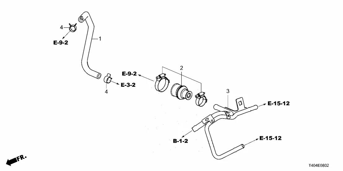
If the CCS were installed on the CCV side, I could see where there could be potential issues since the airflow is bidirectional. Part number 3 in the below PIC would also need to be butchered up where parts 2 and 3 mate together.
11th Gen Honda Civic Improved Racing CCS Catch Can PCV_and_CCV_Connections

Considering that it is a closed system with metered air, is a VTA can on the CCV side a viable solution to keeping the intake track clean?
 

HondaHoon

Senior Member
Joined
Jul 18, 2025
Threads
15
Messages
443
Reaction score
364
Location
Western Maryland, USA
Vehicle(s)
'22 Audi RS5 Comp., '25 CTR, '07 Porsche 911, '23 Ducati Streetfighter
Thanks and that sucks to hear. Thinking some more, it makes sense to me now for the Improved Racing CCS to be installed on the PCV side only. In that configuration, airflow only travels in one direction just like how the CCS was designed to support.

If the CCS were installed on the CCV side, I could see where there could be potential issues since the airflow is bidirectional. Part number 3 in the below PIC would also need to be butchered up where parts 2 and 3 mate together.
PCV_and_CCV_Connections.webp

Considering that it is a closed system with metered air, is a VTA can on the CCV side a viable solution to keeping the intake track clean?
I am not doing it, I am leaving the CCV side alone.


cryptolime

Senior Member
Joined
Oct 21, 2023
Threads
50
Messages
738
Reaction score
391
Location
Wilmington, NC
Vehicle(s)
2023 Civic Si
Radium's CCV system created too much crankcase back pressure on my ride under tracking/modified boost conditions causing the dipstick to pop. I would not recommend putting anything on the CCV side unless venting to a VTA can.
these complications make me think the OEM design is pretty optimized as it is
 

blueroadster

Senior Member
Joined
Apr 19, 2024
Threads
29
Messages
659
Reaction score
941
Location
MD
Vehicle(s)
2024 Civic Type R, 2026 Passport TSE, 2026 Pilot BE, 1964 Impala SS
these complications make me think the OEM design is pretty optimized as it is
Appears so on the CCV side however, the PCV side has shown value in installing a catch can. I decided to order the Improved Racing CCS and will install as designed on the PCV side.
 

PointByPatrol

Senior Member
First Name
Ben
Joined
Jul 28, 2023
Threads
44
Messages
2,022
Reaction score
3,204
Location
NC
Vehicle(s)
2024 Civic Type R
Build Thread
Link
There is a PCV valve in the valve cover, Part no. 17130-RPY-G01

Vacuum from the intake manifold draws flow from the valve cover, with the other side that connects between the intake and turbo inlet providing an input of metered air. In addition to relieving crankcase pressure, this actively pulls out water and fuel vapor that might otherwise condense and fall back into the oil pan.

When the PCV valve (or a check valve after the catch can) is closed, the flow doesn’t just completely reverse to go back into the turbo inlet, because it’s like having only one window open in the house. Air doesn’t circulate like if you have two open windows, hence why CCV cans don’t collect much.

I also think there is an issue with running too long of hoses to a can vs the short section normally between the valve cover and the intake, I think @PointByPatrol mentioned it.
My engine smoked like crazy with the Radium cans, but I'm running a 4p engine with more blowby than stock, so there's something to that, but now I just vent my CCV atmospherically.
 

TypeRD

Senior Member
First Name
Ryan
Joined
Jan 20, 2023
Threads
2
Messages
1,798
Reaction score
1,886
Location
Midwest
Vehicle(s)
2023 Civic Type-R
Don't think I've ever heard a catch can be called sexy đŸ€Ł
Oooohhh
what a hawt can. I’m gonna need a minute.đŸ„”đŸ€Ł
 

Jon_To

Member
First Name
Jon
Joined
Jun 17, 2026
Threads
1
Messages
11
Reaction score
3
Location
Torrance
Vehicle(s)
2026 CTR
Anyone running a front stut bar with this setup? Wondering which one would work without modification or blocking the path to removing the can.


Chilly613

Senior Member
Joined
Nov 5, 2022
Threads
13
Messages
1,120
Reaction score
1,374
Location
Southern California
Vehicle(s)
2025 FL5 Civic Type R
Build Thread
Link
Anyone running a front stut bar with this setup? Wondering which one would work without modification or blocking the path to removing the can.
Depends on the front strut bar. If you have one that sits close to the firewall it should be fine.
 

nycxandy

Member
Joined
Jun 23, 2023
Threads
0
Messages
20
Reaction score
10
Location
NY
Vehicle(s)
?
I have this can and guess what, as usual they used 3/8" lines. You can't use a 5/16" clamp on a 3/8" hose. So now they can either replace them with the proper 5/16" or I am returning it. At $300 I shouldn't have to buy parts to make it work. If you put 3/8" hoses on 5/16" fittings you will have a vacuum leak and your car will run rich. Seems like every catch can maker does this and I have gone through this with multiple vehicles. Also this one does not have a check valve and you should really use one.
Did they rectify this issue and provide you with the correctly sized hose?
 

tc0566

Member
First Name
Jim
Joined
Mar 14, 2026
Threads
0
Messages
20
Reaction score
13
Location
Canton, Ohio
Vehicle(s)
2025 Honda Civic Type R
Did they rectify this issue and provide you with the correctly sized hose?
No, didn't even get a response from their nonexistent customer support. They also wouldn't post my review on their website. Can might look great but they sure as hell don't stand by their product.
 

nycxandy

Member
Joined
Jun 23, 2023
Threads
0
Messages
20
Reaction score
10
Location
NY
Vehicle(s)
?
No, didn't even get a response from their nonexistent customer support. They also wouldn't post my review on their website. Can might look great but they sure as hell don't stand by their product.
It looks like they addressed this topic in the comment section of phothrottle's video.

Comment: "I really love that catch can makers use 3/8 hoses and the vehicles actually use 5/16 hoses. You can not get a good seal and the original clamps are too small to work. Every time I do a catch can I have to supply my own hoses because it will leak vacuum if the hoses are 3/8". And the author did not use the factory clamps on the hoses that come with the catch can, when fully open the clamps are still too small to fit over the hoses that come with the can."

Response: "Hey, We utilize 3/8 hose because Honda uses 9.5mm barbs. The hose we use is a R9 J30 viton hose, which naturally has a thicker sidewall, that does not allow the factor hose clamp to work. I can assure you the hoses on these kits seal, otherwise they would throw a PCV code. Not only that, but Honda uses 9.5mm ID hose, so downsizing from that to 5/16 is a downgrade from the factory. "

Thoughts?
 

tc0566

Member
First Name
Jim
Joined
Mar 14, 2026
Threads
0
Messages
20
Reaction score
13
Location
Canton, Ohio
Vehicle(s)
2025 Honda Civic Type R
It looks like they addressed this topic in the comment section of phothrottle's video.

Comment: "I really love that catch can makers use 3/8 hoses and the vehicles actually use 5/16 hoses. You can not get a good seal and the original clamps are too small to work. Every time I do a catch can I have to supply my own hoses because it will leak vacuum if the hoses are 3/8". And the author did not use the factory clamps on the hoses that come with the catch can, when fully open the clamps are still too small to fit over the hoses that come with the can."

Response: "Hey, We utilize 3/8 hose because Honda uses 9.5mm barbs. The hose we use is a R9 J30 viton hose, which naturally has a thicker sidewall, that does not allow the factor hose clamp to work. I can assure you the hoses on these kits seal, otherwise they would throw a PCV code. Not only that, but Honda uses 9.5mm ID hose, so downsizing from that to 5/16 is a downgrade from the factory. "

Thoughts?
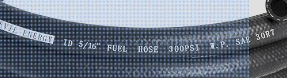
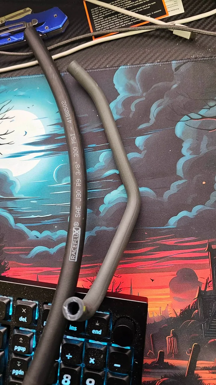
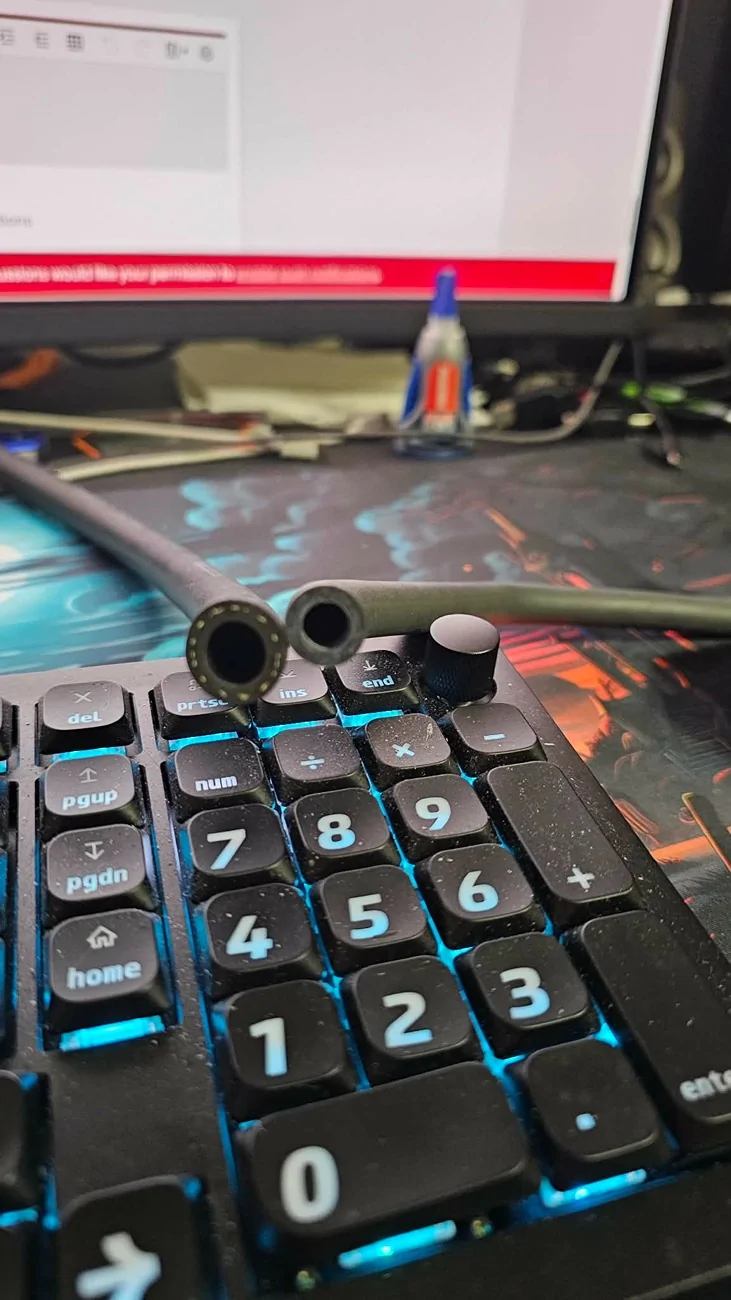
Yeah and I just responded to that. Again the barbs are plastic 5/16. Try tightening those hoses down enough to seal and you'll be replacing the intake and and valve cover. I fixed mine by replacing the hoses with the proper size. 9.5mm are 3/8 and i guarantee those barbs are not 3/8. Here is a pic of the current hose I'm using.

11th Gen Honda Civic Improved Racing CCS Catch Can Screenshot 2026-08-25 184541


11th Gen Honda Civic Improved Racing CCS Catch Can a94bf9df-c8c3-4cdd-8d50-bd9b10b1b94


11th Gen Honda Civic Improved Racing CCS Catch Can 37ca76b6-8b1e-4fa1-b3e7-3f250022ae93
 
Last edited:


Top